- 您现在的位置:买卖IC网 > Sheet目录202 > ACM20-4-AC1-R-F-C (Murata Power Solutions Inc)METER AC POWER 100A W/FREQ READ
ACM20 Series
Four-Function AC Power Meters
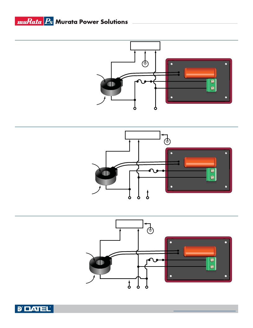
TYPICAL WIRING DIAGRAMS, CONT.
220 V
LOAD
Epoxy en c apsu l ation
Note: If the ACM20 displays zero Watts with
B
T B 1
power applied to the load, reverse the direction
of the wire passing through the CT's center hole.
See Technical Note 6 for more information.
Po l arity dot on bottom
L1
Fuse*
L2
A
220 Va c (50/60 Hz)
Figure 2. Wiring diagram for 220/240V systems with no neutral
1 20 V
LOAD
Epoxy en c apsu l ation
*See technical note 5.
Note: If the ACM20 displays zero Watts with
power applied to the load, reverse the direction
of the wire passing through the CT's center hole.
Fuse*
B
A
T B 1
See Technical Note 6 for more information.
Po l arity dot on bottom
L 1 Neutra l L2
220 Va c (50/60 Hz)
Figure 3. Wiring diagram for 120/240V systems with neutral (monitoring L1)
1 20 V
LOAD
Epoxy en c apsu l ation
*See technical note 5.
Note: If the ACM20 displays zero Watts with
B
T B 1
power applied to the load, reverse the direction
of the wire passing through the CT's center hole.
See Technical Note 6 for more information.
Po l arity dot on bottom
L 1 Neutra l L2
220 Va c (50/60 Hz)
Fuse*
A
*See technical note 5.
Figure 4. Wiring diagram for 120/240V systems with neutral (monitoring L2)
www.murata-ps.com/support
MPM_ACM20 Series.B03 Page 4 of 6
发布紧急采购,3分钟左右您将得到回复。
相关PDF资料
ACM3P-4-AC1-R-C
AMMETER LED 85-264VAC 100A RED
AD5721R3
SWITCH ROLLER LEVER ASSMBLY
ADA3721R8
SWITCH ROLLER LEVER ASSMBLY
ADD1721R21
SWITCH ROLLER LEVER ASSMBLY
ADH3721R2
SWITCH ROLLER LEVER ASSMBLY
ADT3723R
SWITCH ROLLER LEVER ASSMBLY
AE101SD1AQ04
SW TOGGLE SPDT 5AMP PCB
AE211MD1CB04
SWITCH TOGGLE SP3T 0.4VA T/H
相关代理商/技术参数
ACM20-5-AC1-B-C
功能描述:Multifunction Meter (Current, Voltage, Wattage) LED - Blue Characters Display Panel Mount - Surface 制造商:murata power solutions inc. 系列:ACM20 零件状态:有效 类型:万用表(电流,电压,瓦特) 测量范围:0 ~ 100A 显示类型:LED - 蓝色字符 每行字符数:4 显示字符 - ?高度:0.360"(9.14mm) 输出类型:- 电压 - 电源:85 ~ 264VAC 面板开口尺寸:矩形 - 36.22mm x 22.10mm 安装类型:面板安装 - 表面 端子类型:螺丝端子 侵入防护:- 特性:内置电流互感器(初级) 工作温度:0°C ~ 60°C 重量:0.096 磅(43.54g) 标准包装:12
ACM20-5-AC1-B-F-C
功能描述:Multifunction Meter (Current, Voltage, Wattage, Frequency) LED - Blue Characters Display Panel Mount - Surface 制造商:murata power solutions inc. 系列:ACM20 零件状态:有效 类型:万用表(电流,电压,瓦特,频率) 测量范围:0 ~ 100A 显示类型:LED - 蓝色字符 每行字符数:4 显示字符 - ?高度:0.360"(9.14mm) 输出类型:- 电压 - 电源:85 ~ 264VAC 面板开口尺寸:矩形 - 36.22mm x 22.10mm 安装类型:面板安装 - 表面 端子类型:螺丝端子 侵入防护:- 特性:内置电流互感器(初级) 工作温度:0°C ~ 60°C 重量:0.096 磅(43.54g) 标准包装:12
ACM20-5-AC1-G-C
制造商:Murata Power Solutions 功能描述:AC POWR METER-30A, POWR FACTR
ACM20-5-AC1-G-F-C
功能描述:MULTI METER 0-32A LED PANEL MT 制造商:murata power solutions inc. 系列:ACM20 零件状态:在售 类型:万用表(电流,电压,瓦特,频率) 测量范围:0 ~ 32A 显示类型:LED - 绿色字符 每行字符数:4 显示字符 - ?高度:0.360"(9.14mm) 输出类型:- 电压 - 电源:85 ~ 264VAC 面板开口尺寸:矩形 - 36.22mm x 22.10mm 安装类型:面板安装 - 表面 端子类型:螺丝端子 侵入防护:- 特性:内置电流互感器(初级) 工作温度:0°C ~ 60°C 标准包装:12
ACM20-5-AC1-R-C
功能描述:数字面板表 30A 85-264Vac Supply Power Factor Reading
RoHS:否 制造商:Murata Power Solutions 设备类型:AC Voltmeters 显示器类型:LED, 3 Digit, Red 工作电源电压:85 VAC to 264 VAC 工作电源电流:50 mArms 输入电流:50 mA 输入频率: 输入电压:120 VAC 系列:DMS-20PC-1-LM
ACM20-5-AC1-R-F-C
功能描述:数字面板表 30A 85-264Vac Supply Frequency Reading
RoHS:否 制造商:Murata Power Solutions 设备类型:AC Voltmeters 显示器类型:LED, 3 Digit, Red 工作电源电压:85 VAC to 264 VAC 工作电源电流:50 mArms 输入电流:50 mA 输入频率: 输入电压:120 VAC 系列:DMS-20PC-1-LM
ACM21
制造商:ABRACON 制造商全称:Abracon Corporation 功能描述:SMD COMMON MODE CHOKE
ACM-21-121M-T
功能描述:2 Line Common Mode Choke Surface Mount 120 Ohm @ 100MHz 370mA DCR 300 mOhm 制造商:abracon llc 系列:ACM-21 包装:剪切带(CT) 零件状态:有效 滤波器类型:信号线 线路数:2 不同频率时的阻抗:120 欧姆 @ 100MHz 电感 @ 频率:- 额定电流(最大):370mA 直流电阻(DCR)(最大):300 毫欧 额定电压 - DC:50V 额定电压 - AC:- 工作温度:-40°C ~ 85°C 等级:- 认可:- 特性:- 安装类型:表面贴装 大小/尺寸:0.079" 长 x 0.047" 宽(2.00mm x 1.20mm) 高度(最大值):0.055"(1.40mm) 封装/外壳:水平式,4 PC 板 标准包装:1
